Network tab
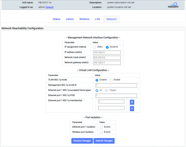
The top half of the Network tab contains Network Reachability Configuration settings. They include settings for Management Network Interfaces, VLAN Configuration and Port Isolation.
Network tab — Network Reachability Configuration section
Management Network Interface Configuration
By default, AltoPlex radios use dynamic IP address assignment and, beginning with release 3.6.0, have a factory default fallback static IP address of 192.168.0.1. Additionally:
- Radios can be configured to use a static IP address, rather than dynamic IP address assignment. This will override the factory default fallback IP.
- Radios upgraded to release 3.6.0 that have not been factory reset will have a factory default fallback IP address of 192.168.0.51, unless they have a configured static IP address that overrides the default address.
- For radios with a firmware release prior to 3.6.0, the factory default fallback IP address will be the address that was included on the sticker when the device was originally shipped.
Click Static to configure the radio to use a static IP address rather than dynamic IP address assignment. Configure the IP address, Network mask and Network gateway.
Virtual LAN Configuration
With AltoPlex technology, a radio operating in a Distribution Node role establishes a wireless link with a device in a client node role when that client is installed and added to the CN responder list. Once connected, the clients remain reachable for management traffic regardless of VLAN settings. This operation eliminates a problem seen with Gen2 (802.11ad) technology where incorrect VLAN settings could render a device unreachable via airlink.
VLAN 802.1q mode — Select Enable to enable VLAN support on this radio.
Management 802.1q VLAN ID — The identification number of the VLAN used for management purposes.
Ethernet port x 802.1q accepted frame types — For VLANs that the port is a member of, accept All incoming Ethernet packets, or only packets that are Tagged.
Ethernet port x 802.1q PVID — The Port VLAN ID (PVID). This determines what VLAN ID will be assigned to untagged frames.
Ethernet port x 802.1q membership — The VLANs that this Ethernet Port is a member of. Allowed values are single integers, a range of integers, or both. Values should be comma-separated without spaces. For example, 1,6,10-15. Maximum value is 4094.
Ethernet port x isolation — Click Enabled to restrict traffic between nodes in the VLAN over the Ethernet interface.
Wireless port isolation — Click Enabled to restrict traffic between nodes in the VLAN over the Wireless interface.
Network tab — Spanning Tree Protocol Configuration
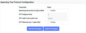
Spanning tree protocol — Enable/disable spanning tree protocol (STP) by checking/clearing the box. If enabled, optionally set the bridge priority and port path cost for the wireless interface.
STP bridge priority is used to determine which device will serve as the root of the spanning tree. The device with the lowest priority will serve as the root. The priority configured here is a multiplier; to determine the actual STP priority, multiply by 4096.
The STP port path cost is used to determine the preferred path to the root. The path with the lowest cumulative cost is used.
The STP Ethernet port 1 bpdu filter prevents BPDU packets from being forwarded, which allows for separate networks to be isolated from participating in the same STP environment. When enabled, the filter is applied whether or not Spanning Tree Protocol is enabled.
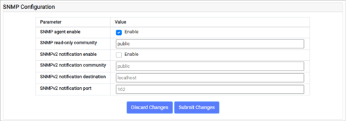
Network tab — SNMP Configuration
Simple Network Management Protocol (SNMP) is used to monitor devices on a network for performance and error information. The settings in this section enable/disable SNMP and configure notification and community access settings.
The Altowav enterprise MIB can be downloaded at https://www.altowav.com/technology/assets/pdf/ALTOWAV-MIB.mib.
Network tab — Network Services Configuration
DNS IP list — A list of DNS server IP addresses using commas to separate the addresses.

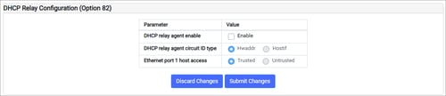
Network tab — DHCP Relay Configuration (Option 82)
Enable the DHCP relay agent to:
- Prevent unauthorized DHCP servers from serving IP addresses to devices on your network.
- Insert a circuit ID into a DHCP message that identifies the source of the message. The DHCP relay agent circuit ID type can be either HWaddr (the MAC address of the DN's Ethernet port, in ASCII format), or the Hostif (the hostname:Ethernet_port of the DN in ASCII format).
You can also select whether the Ethernet port is:
- Trusted — All DHCP packets coming from devices attached to the Ethernet port will be forwarded.
- Untrusted:
- All DHCP server packets from attached devices will be blocked.
- All DHCP client packets from attached devices that have option 82 information in their header will be blocked.
- All DHCP client packets from attached devices that do not have option 82 information in their header will be fowarded, with the circuit ID appended.
All wireless links are automatically considered trusted.