The Map page shows the site's network topology in an interactive map. The map uses a Google Maps base with familiar controls for zoom, scroll and switching between map and satellite views.
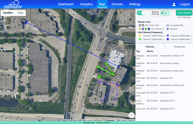
The Map key is at the top of the right sidebar, showing symbols for markers and colors used for each channel. You can hide the key by toggling off the Key toggle ( ). You can also set the Refresh Interval to configure how often AltoCommand refreshes data on the Map, and set the Time Period the configure the period of time that AltoCommand uses to compute average throughput. The Pointer icon (
 ) next to a label indicates that clicking the label will toggle the category on and off.
Wireless links are shown as solid lines on the map. Channels are displayed in specific colors and down links are displayed in blinking red, to enable quick visualization of real time problems, and which channels are being used in each area.
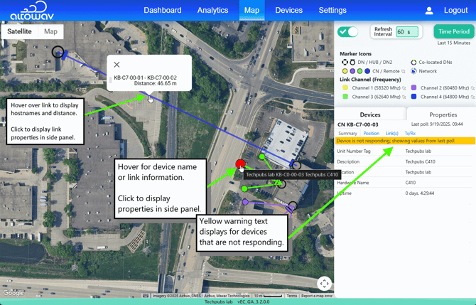
Hover over or click on a device or link to provide detailed information.
- Devices:
- Hover over the device to display the hostname, location, and description.
- The Devices tab in the sidebar lists all devices with with their tag and hostname. Click a device in the list or on the map to display a summary in the Properties tab.
- Links:
- Hover over a link on the map to display the hostnames of the linked devices and the distance of the link, in meters.
- Click the link to show one of the linked devices in the sidebar, with the Link Properties displayed. Click the link again to show the link properties from the other device.
Device GPS automatically positions DNs on the map, when available. (For Hubs or DNs without GPS enabled, the Map holds the device markers in a tray, until they are dragged to their accurate position.) Markers for connected CN and Remotes are positioned near their connected device. Adjust CN and Remote positions as they are installed to keep the map up-to-date.
The bearing (azimuth) for each DN or Hub should be adjusted manually on the Map, using the compass tool, described in the Properties tab section below.
Using the Map with multiple Networks
When multiple Networks have been configured for your instance of AltoCommand, all Networks selected in the Networks pulldown are displayed on the Map. See Filter displayed information based on Networks for more information about displaying multiple Networks in AltoCommand.
When multiple Networks are selected, the Map displays each network by using a Network icon ( ), and the geographical extent of each Network is indicated by a yellow bounding box.
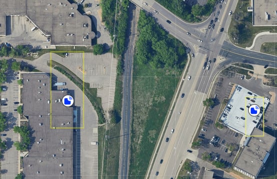
Hover over the Network icon to see the Network name, and click a Network icon to give focus to that Network. The map will zoom into the geographical location of the Network with focus, and display its devices.
You can view the other networks by zooming out until you see their Network icon and yellow bounding box.
Co-located devices
Devices that are installed close to each other (for example, on
the same pole) are considered co-located devices. When possible, AltoCommand will use GPS positioning information to display co-located devices as joined together on the same marker.
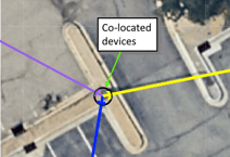
Because of the imprecision of GPS data, some co-located devices may be indicated on the Map as near each other, but not co-located. You can drag the devices to their correct location and join them together to indicate on the map that they are co-located:
- If the first device is not in the correct location, drag the device to the correct location.
- Click on the second device and begin dragging it. An x will appear inside the device marker.
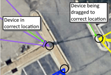
- Drag the incorrectly-located device on top of the black marker for the correct device.
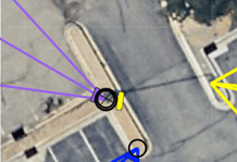
- Drop the device into place.
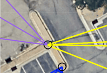
- Repeat for any other co-located devices.
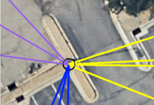
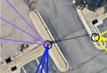
Another possibility is that AltoCommand may incorrectly determine that two or more devices are co-located, when they are in fact near to each other but in different locations. To rectify this situation:
- Click on the marker for the co-located devices and drag to an alternate location.
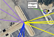
- Drop the device marker. This will place one of the devices in the new location, and will return the other devices to the original (co-located) location.
The Map side panel
The Map side panel, displayed to the right of the map, displays a map key, configurable refresh interval and time period for computing average throughput, and device information.
Devices tab on the side panel
The Devices tab lists all devices shown on the map. Quickly locate a device on the map by hovering over it in the list of Devices - the map marker for the device enlarges. Or, hover over a map marker and the device name is highlighted in the list.
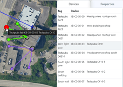
The device's Tag is extracted from the device's Description or Location fields.
- The Tag for a DN device is the device's configured description.
- The Tag for a CN device is the device's configured location.
See the device documentation for information about how to configure the description and location.
Consistent information for Descriptions and Locations will result in an easier-to-use list in this area of the Map.
Properties tab on map side panel
Click on a device in the list or on the Map to show its Properties. For co-located devices, clicking on the co-location marker on the Map will sequence through each co-located device and display that device's Properties.
The Properties tab has four sub-tabs — Summary, Position, Link(s) and TX/RX throughput:
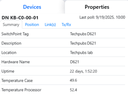 |
Summary DNs — Switch point tag, Description, Location, Hardware Name, Uptime and temperatures for the case and processor. CNs — Unit Number Tag, Description, Location, Hardware Name and Uptime. K60 — Switch point tag (Hub), Unit Number Tag (Remote), Description, Location, and Uptime. |
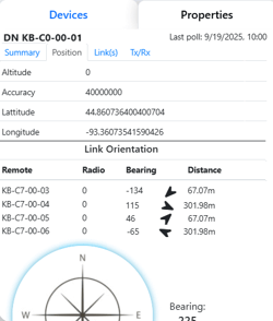 |
Position DNs — GPS values for Altitude, accuracy, latitude, and longitude are shown. Link Orientation information is bearing and distance information taken from the map. The links listed are from the DN's configuration. They may be active or inactive. When a DN marker is manually repositioned on the map, a Reset button appears. Click it to move the marker to the device's polled GPS location. K60 — Latitude and Longitude are listed as shown on the map. Link Orientation information is bearing and distance information taken from the map. Drag the marker to the actual location. Links listed are from the K60's configuration. They may be active or inactive. |
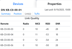 |
Link(s) DNs — Remote devices, including the radio interface, MCS, RSSI and SNR for each link. Click on a link to show the attributes of the linked device. CNs — Remote DN, Remote MAC, RF Channel, Power, MCS, RSSI, SNR, Link Uptime, Link Up Attempts, Link Up/ Data down statistics, RX Beam Index, TX Beam Index, Link Name and Link Description. K60 - Hubs list remote names, MCS, RSSI and LinkQ are shown for each link. Remotes list the Remote Hub, Channel, TX Beam Index, RX Beam Index, MCS, RSSI and LinkQ are listed. |
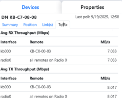 |
TX / RX Shows throughput statistics for all interfaces on the device. This represents the average throughput during the most recent time period, as configured by using the Time Period button at the top of the side bar. |
Adjustments for Map accuracy
Whether setting up an initial network or adding / removing devices, adjusting devices' positions and bearings enhances the accuracy and usefulness of the Map. Common adjustments per device type:
DN or Hub devices
- For devices with GPS disabled or unavailable, drag the device from the tray to the installed location on the map. Devices with active GPS are automatically positioned at their GPS location.
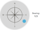
- Use the compass on the Properties > Position tab to set the azimuth per the actual installation. Drag the circle on the compass to the device's actual azimuth. For K60DNs, use the Radio 0 azimuth.
CNs or Remote devices
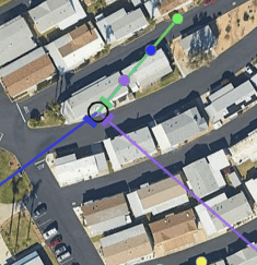
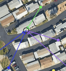
Map markers for CNs or Remotes are added to the map near the DN or Hub to which they connect. Drag the CN markers to their actual installed location on the map.
|
|
|
| Client nodes at initial location on the Map. | Client nodes moved to their correct location on the Map. |