These instructions cover the preparation of the Line AC terminal and weatherproof installation of cable into the PoE ports. Examples of mounting the PoE switch are also provided.
Note: Link Layer Discovery Protocol (LLDP) is required for correct LAN peer identification when using multiple AltoPlex devices at one switch point. The outdoor PoE switch supports LLDP. If another switch is being used, LLDP must be supported and enabled on that switch.
|
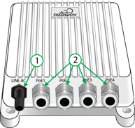
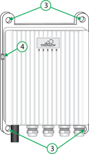
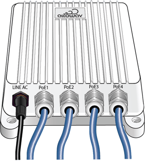
1. Line AC power input port with waterproof cap and gland. 2. Power over Ethernet (PoE) ports with waterproof glands. |
3. Mounting holes. 4. Ground. |
 |
 |
Install AC power
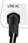
- Unscrew the waterproof cap and gland from the Line AC power input port.
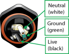
Temporary pigtail wires indicate correct wire placement, as shown.

- Disassemble the waterproof cap and gland.


- Using an SO power cord (3-wire 18AWG):
- Strip 25 mm (1 in.) of the cable jacket and 10 mm (3/8 - 1/2 in.) of insulation from each wire.
- Insert the prepared cord into the disassembled cap and gland.


- Using a Phillips-head screwdriver, insert the wires into the correct pin ports one at a time:
- Loosen one screw and remove the temporary pigtail wire.
- Insert the correct wire (live, neutral, or ground) and tighten the screw.
- Repeat for each wire.
- Slide the waterproof gland over the AC input port pins and hand tighten to the housing.
- Hand tighten the cap to the gland.

Install Ethernet cables
- Unscrew and disassemble the PoE Ethernet end caps and glands from the ports on the PoE switch.
- Insert an outdoor-rated Cat6 Ethernet cable in the component parts of the PoE Ethernet end caps and glands. You may need to cut a slit in the rubber grommet from top to bottom, to allow inserting the Ethernet cable.




- Securely plug the RJ45 connector into the RJ45 slot inside a PoE port. Listen for a click to verify a solid connection.
- Slide all cable gland components up the Cat6 and into the PoE port. Components should self-align and seal adequately.
- Fasten the steel end caps securely, but do not over tighten. The goal is tight enough to keep water out, without impacting the internal RJ45 connection.
- Repeat the end cap reassembly for the remaining RJ45 connections.
Examples of outdoor PoE switch installation
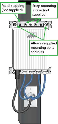
Metal pole mount
Additional required equipment (not supplied):
- Metal strapping and screws.
- Outdoor electrical faceplate and clamp cable connector.
Wood pole with conduit mount
Additional required equipment (not supplied):
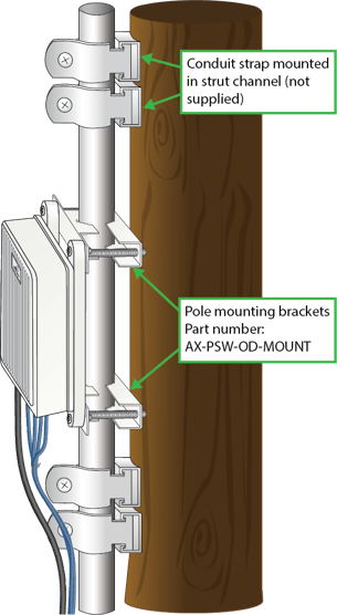
- Pole mounting bracket, Altowav part number AX-PSW-OD-MOUNT
- Conduit
- Conduit straps
- Strut channel