
Altowav recommends creating a detailed network design and deployment plan with specific device, network and location information. The following example is a general illustration of a network design plan; your specific situation will vary. Channel and golay code settings should be selected based on the deployment specifics; see Design Issues to Avoid for details about using channel and golay code settings.
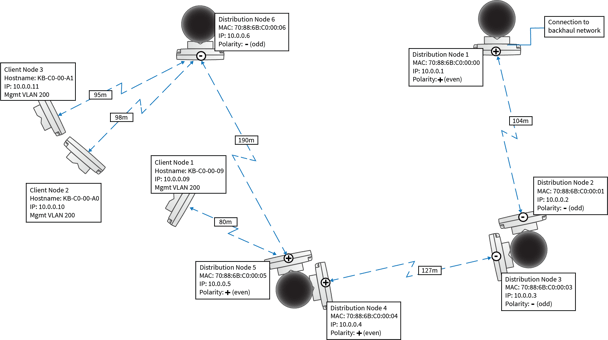
Considerations for all deployments:
- Generally, all DNs on the same pole should have the same polarity. If your network requires opposite polarities on the same pole, make sure that the devices are set to different channels.
- Keep in mind performance and operational characteristics of the DN for range, and throughput, as listed above.
- Follow Installation guidelines.
- Each DN supports one DN link and up to 15 CN links.
Point-to-point deployment
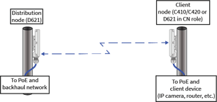
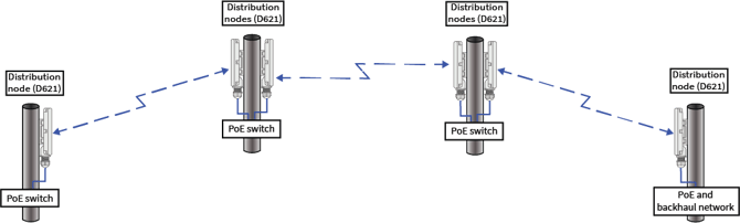
Point-to-point deployments involve either one distribution node and one client node, or two or more distribution nodes linked together in a serial fashion. Select the best role for each end of the link, according to its planned function in the network. At least one radio in the PtP link must be configured as a distribution node.
Point-to-point topology involving distribution node linked to a client node
The following diagram demonstrates a simple point-to-point topology.
Point-to-point topology with multiple distribution nodes (daisy-chain)
The following diagram demonstrates several distribution nodes linked together in a serial fashion.
Point-to-multipoint deployment
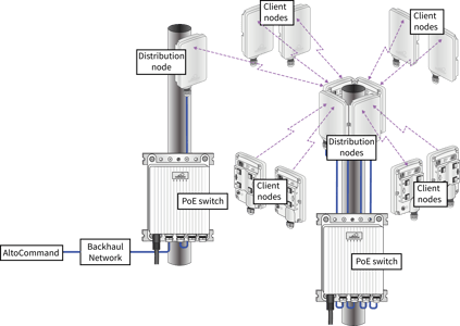
In point-to-multipoint deployments, one distribution node wirelessly connects the backhaul network to distribution nodes networked via a switch.
Ring deployment
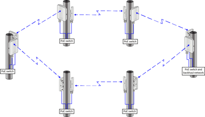
A ring deployment is a standard topology for AltoPlex deployments, and can be used to provide redundant backup network connections by utilizing Rapid Spanning Tree Protocol (RSTP). RSTP should be enabled for ring topologies. RSTP is enabled by default on the D621 and D423 and disabled by default on dedicated client nodes (C410 and C420).
Spur or Spoke Deployment
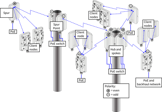
A spur or spoke deployment extends the reach of a distribution network. At least two DNs are required at the spur switch point that extends distribution to a wider azimuth range.
Design Issues to Avoid
The following describe common problems with design issues for 60GHz networks running on 802.11ay-based technology.
Issue: Tight angles between DN links and CN links
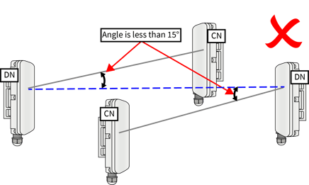
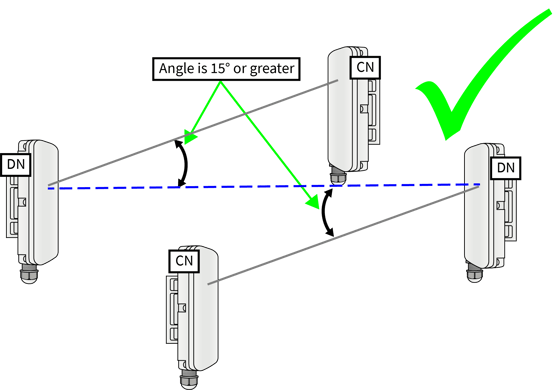
Tight angles between the DN link and the CN link in the same sector, such as the butterfly topology, can result in early weak interference.
This problem occurs at angles tighter than 15°. Early weak interference can be hard to detect because it does not create any signal-to-interference-plus-noise ratio (SINR) degradation, but it still blocks desired packets by locking the receiver before the arrival of the packet.
Best Practice:
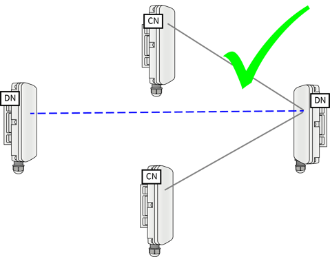
If the client nodes cannot be positioned to avoid the tight angle, the best workaround is to link both client nodes to same distribution node.
Ideally the client nodes would link to the distribution node closest to the point of presence (PoP) . This will minimize the number of hops from the PoP to the client node. This ideal is not always practical, due to site conditions and line of sight.
Additional Solution:
Design and deploy sites where the CN links are more than 15° away from the DN links as shown in the butterfly topology diagram below.
Issue: Distribution nodes in a straight line and close together
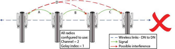
When three or more DN links are in a line and are using the same channel and golay code, a signal can be far reaching and cause interference to an unintended endpoint. Straight line interference is more impactful for short link distances.
The diagram below shows transmission using the same channel and golay index. In this case, signal A can also cause a signal D that may interfere with an unintended endpoint.
Solutions:
- Set the Golay index (1-3) for both ends of each link. Make sure that the Golay index is different for the link between the two DNs with the possible signal interference.