
Box contents
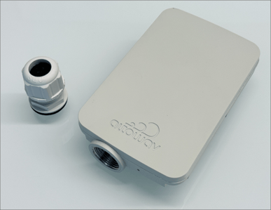
- D621 device.
- IP67 cable gland.
- QR code card for D621 Quick Start and D621 User Guide.
- Also available:
- Wall Mount
- Model number: AX-AW3-MT-WALL
- Extended Range Pole Mount
- Model number: AX-AW3-MT-EXT.
- Indoor Power over Ethernet (PoE) injector:
- Model number AX-P-IN-AT-5G
- Outdoor PoE switch:
- Model number AX-PSW-OD-4AT-4C25
- Mounting bracket: Model number AX-PSW-OD-MOUNT
- Wall Mount
About AltoPlex D621 distribution nodes (DN)
The D621 supports the AltoPlex series for 60 GHz wireless networks and provides wireless coverage for a 90° sector. See the D621 datasheet for specifications and features. See Design and Deployment for general design and deployment information, best practices and considerations based on network topology.
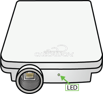
The 2.5 Gbps RJ45 port and LED are located at the base of the unit.
Ethernet port and LED of the D621
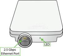
The red/green LED on the bottom of the D621 device shows power, connection and activity.
- Red — powering up.
- Flashing red and green — during boot up.
- Flashing green — until at least one wired link and one wireless link is formed.
- Steady green — normal operations with one or more wired and one or more wireless link.
See LED Indicators for more detail.
Installation
Installation tips:
- Install the D621 on the pole or wall with no obstructions above the unit to allow for GPS synchronization.
- Maintain clear line of sight (LOS) at the front of the D621 so that links to other radios can be formed. Best performance is achieved with boresight alignment between D621 wireless devices, so this is recommended for DN to DN links. Because AltoPlex devices use a wide-angle beam pattern that can scan across a 90° horizontal and +/-20° vertical air space, boresight is not required but will create the strongest link.
- Power source: For outdoor use, the 4 Port 2.5G PoE switch (Altowav Model AX-PSW-OD-4AT-4C25) is recommended. This outdoor PoE switch can provide power for up to four connected devices. If weatherproof enclosure is available on site and power for only one device is required, the optional AX-P-IN-AT-5G (30 W indoor PoE injector) can be used.
If a customer-supplied switch is used: To take advantage of the LL discovery feature, the switch should support LLDP and it should be enabled. Also be aware that managed switches with Rapid Spanning Tree Protocol (RSTP) enabled increase the hop count for RSTP. See Network tab — Spanning Tree Protocol configuration for details about configuring AltoPlex devices for RSTP.
- When adjustments to positioning or aiming the D621 are done after the device is linked to other devices, power cycle the unit. To power cycle, simply disconnect the device from power and reconnect it.
Installation procedure
A clear line of sight must be maintained for an optimal wireless link, preferably at boresight for DN links.
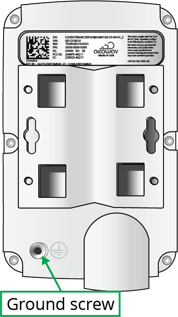
- Install the ground wire, if required by code, at the installation location. Connect the other end of the ground wire to nearby good earth. The ground screw on AltoPlex devices is a #6-32 5/16th inch Phillips head screw.
- Install an outdoor-rated Ethernet cable through the provided cable gland and into the port on the D621 device:
- Unscrew and deconstruct the components of the gland.

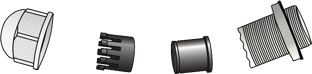
- Insert an outdoor-rated Cat6 cable in the gland as shown.

- Secure the components of the gland and attach the Cat6 cable to the device's RJ45 port and attach the gland to the device. Do not overtighten.
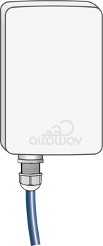
- Unscrew and deconstruct the components of the gland.
- Mount the device to a wall or pole at the installation location with the mounting bracket (see Mounting bracket). Ensure a clear line of sight to the connecting distribution node and no obstructions to GPS above the unit. Orient the D621 according to the planned azimuth and elevation.
- Connect the other end of the Cat6 cable to a Power over Ethernet (PoE) injector or switch. PoE options available from Altowav include:
- Indoor PoE injector, part number AX-P-IN-AT-5G.
- Outdoor PoE switch, part number AX-PSWOD-4AT-4C25.
- Outdoor PoE swtich mounting bracket, part number AX-PSW-OD-MOUNT.
- Verify that the device powers up. (LED is red during boot-up and then flashing green.)
- If other D621s will be installed at the same site (for example, on the same pole), install them according to the design plan. Devices connected through a PoE switch at the same site will become LAN peers via their wired connection through the PoE switch.
- Move to the next site and mount the D621 that will link to the first D621.
- Mount the connecting device.
- Power up.
- Perform DN link auto-configuration.
If DN link auto-configuration isn't used, all devices should be configured prior to mounting the devices.
- For multi-link daisy-chain or ring topologies, install the remaining D621 devices according to the detailed network plan.
- If DN link auto-configuration is being used in the field, configure each DN link in the field as the devices are installed.
If the D621 is repositioned or re-aimed after DN connections are made, rebeamform the link by resetting the DN responder on one end of the link, rebooting, or power cycling the unit. Resetting the responder is the least disruptive method to an operational network.
- Verify that each D621 is connected to the correct DN . This sample of the Wireless table on the Status tab shows the D621 connected to another DN (KB-C0-00-01).

- Check signal quality. For example, a D621-D621 link should have an RSSI of greater than -65. Expected MCS for a D621-D621 link is 9 for up to 250 m, and 12 for up to 150 m with significant traffic.
- If DN link auto-configuration is being used in the field, configure each DN link in the field as the devices are installed.
- After all DNs have been installed and linked, install client nodes one at a time, linking each to the appropriate DN. See Configure links to client nodes for information about linking CNs.