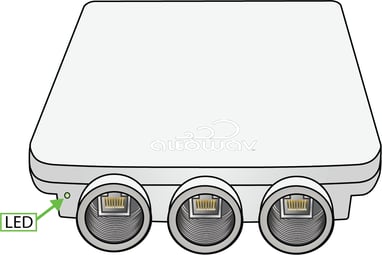
C423 box contents
- C423 device.
- IP67 cable glands.
- QR code card for C423 Quick Start and C423 User Guide.
- Also available:
- Wall Mount
- Model number: AX-AW3-MT-WALL
- Extended Range Pole Mount
- Model number: AX-AW3-MT-EXT
- Wall Mount
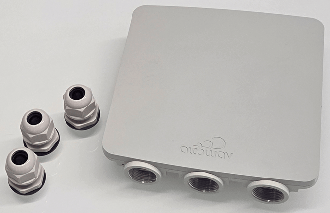
About the AltoPlex C423 distribution node
The C423 supports the AltoPlex series for 60 GHz wireless networks and provides wireless coverage for a 90° sector. See the for specifications and features. See Design and Deployment for general design and deployment information, best practices and considerations based on network topology.
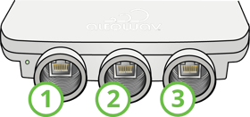
The 1.0 Gbps RJ45 ports and LED are located at the base of the unit.
Ethernet ports and LED of the C423
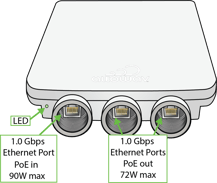
The red/green LED on the bottom of the C423 device shows power, connection and activity.
- Red — powering up.
- Flashing red and green — during boot up.
- Flashing green — until at least one wired link and one wireless link is formed.
- Steady green — normal operations with one or more wired and one or more wireless link.
See LED Indicators for more detail.
Installation
Installation tips:
- Install the C423 on the pole or wall with no obstructions above the unit to allow for GPS synchronization.
- Maintain clear line of sight (LOS) at the front of the C423 so that links to other radios can be formed. Because AltoPlex devices use a wide-angle beam pattern that can scan across a 90° horizontal and +/-20° vertical air space, boresight is not required but will create the strongest link.
- Power source: Power the C423 with a CE certified, standard IEEE Type 4 802.3bt Class 8 90W PoE injector or PoE switch.
If a customer-supplied switch is used: To take advantage of the LL discovery feature, the switch should support LLDP and it should be enabled. Also be aware that managed switches with Rapid Spanning Tree Protocol (RSTP) enabled increase the hop count for RSTP. See Network tab — Spanning Tree Protocol configuration for details about configuring AltoPlex devices for RSTP.
- When adjustments to positioning or aiming the D423 are done after the device is linked to other devices, power cycle the unit. To power cycle, simply disconnect the device from power and reconnect it.
Installation procedure
A clear line of sight must be maintained for an optimal wireless link, preferably at boresight for DN links.
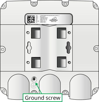
- Install the ground wire, if required by code, at the installation location. Connect the other end of the ground wire to nearby good earth. The ground screw on AltoPlex devices is a #6-32 5/16th inch Phillips head screw.
- Install an outdoor-rated Ethernet cable through the provided cable gland and into port 1 on the C423 device:
- Unscrew and deconstruct the components of the gland.

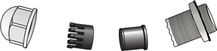
- Insert an outdoor-rated Cat5e (minimum) cable in the gland as shown.

- Secure the components of the gland and attach the Cat5e cable to the device's RJ45 port and attach the gland to the device. Do not overtighten.
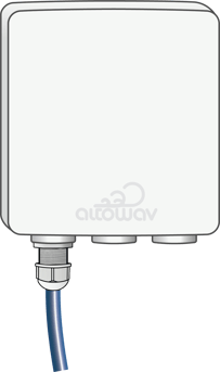
- Unscrew and deconstruct the components of the gland.
- Repeat the above steps as necessary for ports 2 and 3.
- Mount the device to a wall or pole at the installation location with the mounting bracket (see Mounting bracket). Ensure a clear line of sight to the connecting distribution node and no obstructions to GPS above the unit. Orient the C423 according to the planned azimuth and elevation.
- Connect the Ethernet cable from port 1 to a CE certified, standard IEEE Type 4 802.3bt Class 8 90W Power over Ethernet (PoE) injector or PoE switch.
- Verify that the device powers up. (LED is red during boot-up and then flashing green.)