
The installation instructions for C410 and C420 radios include:
- Tool list.
- C410/C420 box contents.
- Mounting instructions.
- Functional description.
- A list of the network design information required.
- Installation and configuration steps.
- Configuration example.
Tool List
- 8mm nut driver or slotted screwdriver for band clamp.
- #2 Phillips head screwdriver for wall mount.
Box contents
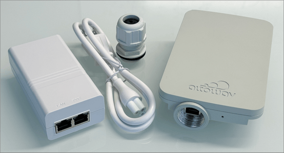
- C410/C420 device.
- IP67 cable gland.
- Indoor Power over Ethernet (PoE) injector and power cord.
- QR code card for C410 and C420 Quick Start and C410 and C420 User Guide.
Mounting brackets
Altowav offers two optional mounting brackets. The two mounting brackets can be used together to provide both azimuth and elevation control.
- The Altowav Wall Mount, model number AX-AW3-MT-WALL.
- The AltoPlex Extended Range Pole Mount, model number AX-AW3-MT-EXT.
Altowav Wall Mount
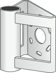
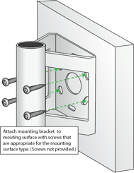
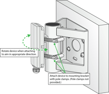
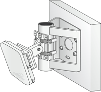
The Altowav Wall Mount, model number AX-AW3-MT-WALL, can be used to securely mount the C410/C420 to a wall or similar flat surface. It can also be used in tandem with the AltoPlex Extended Range Pole Mount to provide both azimuth and elevation control.
| Bracket | Attach to wall or flat surface |
 |
 |
| Attach the C410/C420 to wall mount | Optional installation with the AltoPlex Extended Range Pole Mount |
 |
 |
AltoPlex Extended Range Pole Mount
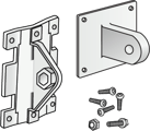
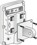
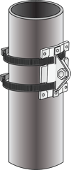
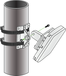
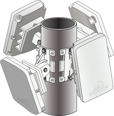
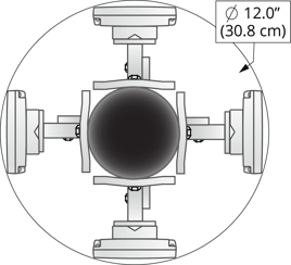
The AltoPlex Extended Range Pole Mount, model number AX-AW3-MT-EXT, enables secure installation and elevation adjustments from +60° to -45°. This model can be used for pole mounting with screws, bolts, or band clamps, and can also be used in tandem with the Altowav Wall Mount, as show above.
| Bracket | Attach to the C410/C420 |
 |
 |
| Pole mounting with band clamps | |
 |
 |
| 360° coverage | Small form factor |
 |
 |
About the C410 and C420
The C410 and C420 are client nodes (CNs) that work in tandem with the D621 distribution node (DN) to provide 60GHz wireless networking connectivity, giving fiber speeds at a fraction of the cost and with rapid deployment. Both models have the same durable and weatherproof outer case.
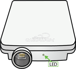
The 1.0 Gbps RJ45 port and LED are located at the base of the unit.
Ethernet port and LED of the C410 and C420
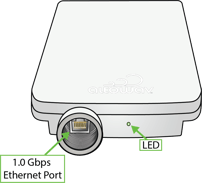
The red/green LED on the bottom of the C410/C420 device shows power, connection and activity.
- Red — powering up.
- Flashing red and green — during boot up.
- Flashing green — until at least one wired link and one wireless link is formed.
- Steady green — normal operations with one or more wired and one or more wireless link.
See LED Indicators for more detail.
Requirements for deployment
These items are required to form a wireless link with an AltoPlex device that is running in distribution node (DN) role:
- Clear line of sight (LOS) to the distribution node.
- The hostname of this device (KB-XX-XX-XX). Listed as HN: on the device label.
- WebUI, CLI, or REST API access to the distribution node for configuration of the client node.
Installation steps
C410 and C420 devices are designed to work out of the box and should not need bench configuration prior to installation and connection.
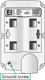
- Install the ground wire, if required by code, at the installation location. Connect the other end of the ground wire to nearby good earth. The ground screw on AltoPlex devices is a #6-32 5/16th inch Phillips head screw.
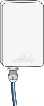
- Install an outdoor-rated Ethernet cable through the provided cable gland and into the port on the C410/C420 device:
- Unscrew and deconstruct the components of the gland.

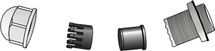
- Insert an outdoor-rated Cat5e (minimum) cable in the gland as shown.

- Secure the components of the gland and attach the Cat5e cable to the device's RJ45 port and attach the gland to the device. Do not overtighten.
- Unscrew and deconstruct the components of the gland.
- Mount the device to a wall or pole at the installation location with the mounting bracket (see Mounting bracket). Ensure a clear line of sight to the connecting distribution node and no obstructions to GPS above the unit. Orient the C410 and C420 according to the planned azimuth and elevation.
- PoE options available from Altowav include:
- Outdoor PoE switch, part number AX-PSWOD-4AT-4C25.
- Outdoor PoE swtich mounting bracket, part number AX-PSW-OD-MOUNT.
- Outdoor PoE switch, part number AX-PSWOD-4AT-4C25.
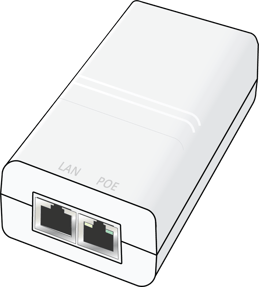
- Connect the other end of the Cat5e cable to the PoE port on the PoE injector or to a PoE switch.
The supplied PoE injector is an indoor unit so it requires a weatherproof box for outdoor installation.
- Verify that the device powers up. (LED is red during boot-up and then flashing green.)
Add the C410/C420 as a client node to a distribution node
The C410/C420 can only operate as a client node (CN) that is attached to a distribution node (DN). This connection is configured on the distribution node after the client node has been installed. This section describes how to add the C410/C420 to a distribution node and complete and verify the installation.
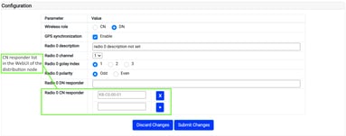
- Add the hostname (KB-XX-XX-XX) of the device to the CN Responder list of the connecting distribution node to initiate a link. In the distribution node's WebUI, the CN Responder list is on the Wireless tab. Click Submit Changes.
The wireless link is formed with no further configuration on the C410 and C420 device, provided that:
- The line of sight to the distribution node is clear.
- The distance to the distribution node is up to 300 meters for a C420 or 200 meters for a C410.
- Network settings for Management VLAN are the same for both devices. The factory defaults work for this.
- After the device connects, review and configure its settings. With the wireless link active, this can be done remotely. C410/C420 Configuration via WebUI provides options for how to access the C410 and C420 WebUI.
- Set the Location and Description on the Admin tab.
- Review settings on the LAN and Network tabs and adjust as required.
- Verify the operation of the new device and review its performance. Adjust for line of sight, and rebeamform as needed. Dress the cable and power cord securely to avoid wear.